Main Gear Legs
Preparation and Installation
"She's got legs, and she knows how to use 'em!"
The main gear come as naked composite forms, with the attachment hole pre-drilled. The first thing is to cover them up. The procedure here, is vastly different from the instructions, but a call into the factory later and I had no issues. The construction manual still talks about covering half the leg at a time, longways, with fiberglass strips. This left a seam, just like the ones running down either side of each leg of a pair of jeans. These seams created a weak point, which could split during a hard landing. To strengthen the design, they replaced the fiberglass strips with carbon fiber "tube socks". They are basically giant Chinese finger traps made out of carbon fiber fabric. When pulled tight, it constricts down to about a 3" diameter, but when squished out, are up to around 10 or 12" diameter. Because you are wrapping the whole leg, at one time, you must either suspend the leg with a eyelet screwed in, or to mount it upside down. I chose to put it in an old bench vise and hold it upside down like that. The reason it has to be upside down for this method, is that the very top 2" do not get wrapped, as they will later get steel cuffs instead.
 |
| A main gear leg installed in a bench vise to apply the carbon fiber reinforcements. |
The carbon fiber tube fabric came as one long roll, enough for 3 layers on both legs. First I measured and cut the carbon fiber for all the legs. For this, I had to use the factory cut lengths, because the final length is almost impossible to measure since they get longer and shorter as they open and close in diameter.

Unlike flat fiberglass lay-ups on vertical surfaces, pre-wetting the cloth with epoxy and the plastic transfer method definitely do not work. This carbon fabric is very thick and epoxy/resin hungry, so I started by a generous wetting of the bare leg, before then slipping the carbon sock over. Once down to the mark for the first sock, I used one hand to hold the sock in place at the bottom, while using my other hand to pull the top of the sock back up, causing the sock to close up and shrink tight around the leg. These carbon fiber socks really take A LOT of epoxy! Once initially wet with epoxy, I used my gloves to directly massage the socks into place, working out any wrinkles or loose spots, until it was smooth, tight, and the grain was as straight as possible. The end result while working these, is that the carbon fiber sock should take on the appearance of a large black snake. Epoxy should fill as much of the texture as possibly, making a very smooth surface, appearing like snake scales. Some texture will remain, but deeper grooves, that don't look "snake like" should be addressed as much as possible.
I learned two very important things about doing these carbon fiber socks.
1) These socks are THIRSTY for epoxy! Unlike the regular fiberglass layups, the name of the game here is how much epoxy can you get onto the sock. This also makes quite a huge mess, but the results are much better.
2) Do not do successive layers while the previous one is wet/sticky. This is the much preferred way of doing successive layups usually; however, in this case, the sticky under layer prevents the new layer from properly sliding and smoothing out. The end result is a pain and an ugly mess that needs a lot of sanding.
 |
| First layer of carbon fiber sock applied and epoxied. Note the snake like smooth texture. |
The down side of doing it one layer at a time, is that every layer has to be sanded smooth and any gaps filled, before the next layer can be applied. I used regular fiberglass epoxy mixed with 50/50 cabosil and cotton flox thickeners, to make a smooth flat surface for the next layer. I highly recommend drilling out the attachment hole each layer. After one layer, you can easily still make the holes out; however, after 3 layers it is impossible to see through the carbon socks.
 |
| Second carbon sock applied and sanded in preparation for the final layer of carbon fiber. |
This process is repeated for all three layers. The final carbon layer ends up longer than the leg, to ensure that is goes all the way beyond the end.
 |
| Final carbon reinforcement sock applied and curing. Note the ragged end, which is well longer than the leg. |
After the third, and final, carbon sock is applied, a thin fiberglass sock is applied over the carbon fiber. The purpose of this layer is not structural or cosmetic, it is chemistry. Bare carbon fiber reacts negatively with aluminum, so the top fiberglass layer is just to keep the carbon fiber reinforcements from interacting with the aluminum parts attached to them.
 |
| The result of 3 layers of carbon fiber and the fiberglass cover. Note the fiberglass layer is nearly invisible, still showing the black carbon fiber beneath. |
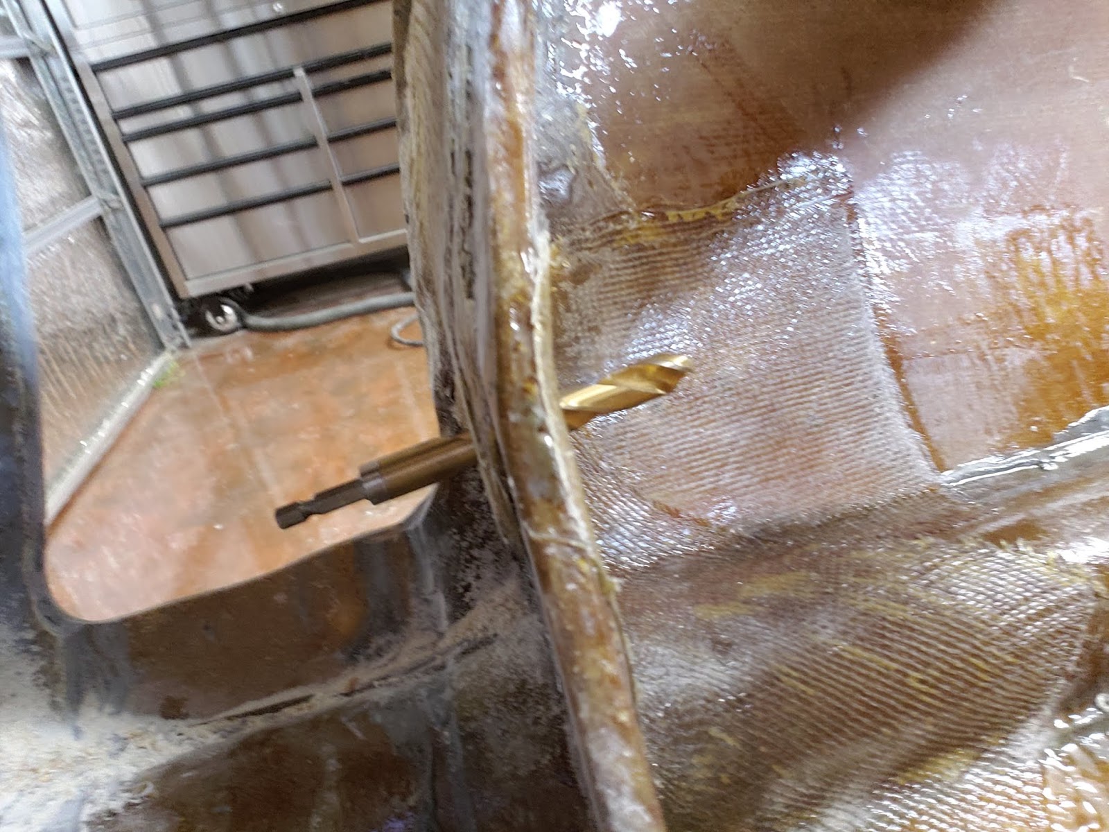
If you don't drill out each layer of carbon fiber, over the attachment hole, you are left with finding it "in the dark". I used a tiny drill bit to test where I thought the hole was, then larger and larger bits to be sure it was only through carbon fiber and not the leg material. I was successful at finding the holes; however, never in the center of the hole, so I had to use a grinder so slowly work out from my hole to the real hole edges.
 |
| The spot of the attachment hole found and opened with a medium drill bit. |
No matter how you find the hole, eventually, you should end up with a hole at least the size of the original hole. Mine ended up beveled, due to slowly looking for the edge of inner hole, without ruining the edge of the hole.
 |
| The attachment hole opened up through the new carbon fiber layers. |
Important Note:
The build manual says this attachment hole is pre-reamed at the factory so not to drill or ream it. This was true when it left the factory; however, when doing the carbon reinforcement layers, some epoxy drains into this hole, causing it to be slightly too small! Not reaming it back out to the correct size will really hurt down the road...
The best option would be to plug the hole with something easily removed later. Unfortunately for me, it's too late. Something squishy and non-absorbent would be ideal.
The instructions recommend marking the axel position on one leg now, so I measured according to the manual and used this pop divot tool to make a fine definite mark in the surface to drill. The drill hole is tiny, and hard to see, but at least it was easier than doing it laying on the floor, while installed in the air frame.
 |
| Using a pop divot tool to make a deep sharp mark for precise drilling. |
 |
| The axel locating hole is tiny and almost impossible to see. |
With the carbon reinforcement layer complete, the next task is to install the steel collars that attach to the top of the legs. The manual says to do this after the legs are installed, but it is a whole lot easier to do now, on the work bench. I do not know about the condition of these collars in other kits; however, I found the condition well below acceptable, but not beyond fixing. Therefore, the first step was to clean these up, until nothing but solid steel was visible.
 |
| My gear leg collars arrived heavily rusty and not acceptable. |
With the collars back to acceptable condition, the first step is to fit them on the gear legs. I brought my carbon layers a little higher than where the bottom of the collars would be, so I could match the two edges, for a better more complete fitment. Then, I applied a nice thick layer of structural adhesive and slid the collars on. I then pushed as much extra adhesive into the gaps as I could, to ensure a full complete attachment.
 |
| Both gear leg tops with structural adhesive applied and a clean fresh collar ready for installation. Note the marking showing left and right gear legs and direction of leading edges. |
 |
| Collar initially fitted, but space still exists around the edges and in the corners, which need to be filled. |
 |
| The flat surface shows the edges and corners are fully filled with structural adhesive for a strong bond. |
When the structural adhesive is dry, it is then sanded smooth. This removed most of the paint on the collars, but no system is perfect.
 |
| The gear leg collar after sanding the adhesive smooth. |
Since most of the paint was sanded off the collars, they needed a new, final, layer of paint.
 |
| A fresh coat of paint, with masking tape for a clean finish. |
 |
| The final result: Steel collars bonded to the leg with a fresh coat of pain. Sure beats the ugly rusted collars! |
The next step was to install the steel tubes the attachment bolts with go through. If you ream the hole, like the manual says not to, the tube should fit tight, but go on without too much force. If you don't ream it, you are in for one tough fight, as I did. One of my tubes ended up about 1/4" shorter than original due to so much pounding, and was way mushroomed out at the top. This was fixed by drilling it back out to 1/2". The second leg, I used the attachment bolt, to apply the forces more evenly, and not damage the tube nearly as much. I installed them so an even amount was sticking out each side. The manual says to leave this till after fitting the legs in the gear pockets, but fewer moving parts is easier to deal with and bushing installation can absorb any needed fine adjustment.
The installation was a simple process of applying structural adhesive around the tube. The chamfered edge of the hole in the carbon fiber allowed a thicker area of adhesive bonding. Which was then sanded smooth, once dry.
 |
| Structural adhesive applied to the hinge tube. |
 |
| Once sanded, even the messiest adhesive job can be nice and smooth. |
With the steel tubes installed, the gear legs are ready for installation; therefore, its time to get the fuselage ready for them! The first step in preparing the fuselage for the gear, was to cut out the fuselage for the gear to come out. According to Scott Swing, do not drill the firewall gear mounting holes, as the manual states, yet; instead, get the fuselage hole opening cut out and then drill the firewall mounting hole where it "works best". More on that later... First the cutting!
I followed the instructions and cut out the marked box for the gear, under cutting it by 1/4". I started with two large hole saw holes in opposite corners with edges the 1/4" from the cut line. Then it was just a matter of using a jig saw to cut straight lines between the holes and each corner.
 |
| To cut the fuselage gear hole, I started with two large holes, using a large hole saw. |
 |
| Working from the edges of the holes, I cut towards the corners. |
 |
| One cut left to cut it out. This shows the progression of cutting out from the holes. |
 |
| Viola! Cut out cleanly just like the instructions said. |
The instructions then say to slowly remove fuselage material as you run the gear up, until the axel hole is level with the bottom of the wing spar. Wow, horrible waist of time!!! looking at the image below, of the fully cut-out fuselage, tell me why I under cut the small square hole and slowly worked up.
After doing the first leg as the manual states, I came up with a much better method, for the next leg.
First cut the marked hole out full size. Then trim, if needed, to get the leg to fit this hole. Now, instead of slowly cutting and cutting higher and higher, here is a trick. The final position is such that the leg, when retracted, just clears the bottom of the spar. Therefore, measure the width of the hole needed for the gear to fit through, then measure that far in front of the bottom lip of the spar. Next, you just connect the current hole with point marked, and follow it up to where the slat bulkheads meet the gear bulkhead. Then do the same for the back of the hole and the front edge of the spar lip. Also note, the flange on the fuselage will have to be cut back, to allow clearance for the gear leg. This method takes about 1/10th the time and the results are 100% as good! There will still be some sanding to get the fit just right, but this saves a lot of time.
 |
| The final shape of the gear cut out, a far cry from the original square hole. |
The top of the gear pocket/spar support needs a large piece cut out, to allow the gear to come up through it. The inside of the spar support also needs to be cut for the top of the gear leg, when the gear are fully extended. The manual does not give any indication of how far to cut; personally, I cut aggressively, because I can easily go back and put a spacer in to limit travel, if needed.
 |
| The final spar support cut out, to allow the gear to retract fully. |
 |
| The gear leg top in the notch cut out of the spar support to allow full extension. |
 |
| The view of the spar support from the outside looking through the gear leg cut out. Note the large area cut out for the gear to raise through, and the smaller notch for the gear leg top, when fully extended. |
The gear are temporarily installed to fit the cut outs in the spar support and refine the fit of the fuselage cut out. At this point, there is only the one hole in the gear bulkhead, to put the gear attachment bolt through; therefore, the gear is loose and able to move freely, without a hole in the firewall yet. Lots of fine grinding to get the gear to go all the way up and down is required. I really took my time here, and made sure for the best possible fit, with the most range of movement.
I highly suggest buying 2 cheap 1/2" x 10" bolts at the hardware store, to reduce wear and tear on the expensive real bolts.
 |
| Initial fitment of the first gear leg. Note the rear part of the cutout goes straight up toward the bottom of the spar, until I realized it had to go higher than that. Another problem with following the manual's method. |
 |
| With the gear full retracted, it should just barely clear the front edge of the bottom of the spar. |
 |
| The manual says it only needs to go up to the point the axel hole is level with the bottom of the spar, but I worked it until the whole leg fit level with the spar bottom. |
With the fuselage ready for the gear to be installed, it was time to locate and drill the hole in the firewall, to hold the back side of the attachment bolt. After trying a few things, I came up with a really good trick. The problem was that the gear leg had to be held in a very precise position, while the firewall was marked for drilling. Then that mark had to relate to a precisely drilled hole. I used the concept of using the pop divot tool, to make a divot, so the drill bit wouldn't walk. Therefore, I sharpened one of the attachment bolts on my bench grinder. Then once I had the gear leg, in just the right spot, I hit the bolt with a hammer. This held it in place enough to run the leg up and down, and ensure it was aligned perfectly. Then I gave it another good hit, to make sure the divot was deep and easy to use.
 |
| The gear lined up and ready for drilling. |
The correct alignment was pretty difficult to find. It was found where the gear fit in front of the main spar when retracted, with the tops of each lined up with each other and returning to the right spot when extended.
 |
| My modified attachment bolt / divot tool for marking the firewall drill spot. |
With the divot marked on the firewall, I removed the gear leg to drill out the hole. To drill the hole, I bought a 12" long 1/2" drill bit. I had already drilled out the gear bulkhead hole to 1/2", to put the attachment bolt through, while fitting the fuselage hole; therefore, I had to drill the firewall out to 1/2", so the gear bulkhead hole would align the drill bit correctly. A smaller hole would have allowed the gear bulkhead side to move, thus changing the angle of the hole out of alignment.
 |
| The 1/2" x 12" drill bit drilling out the firewall hole. |
With the firewall hole drilled, I reinstalled the gear legs, to ensure they fit correctly. There was still time to correct any problems, if needed.
 |
| The sharpened attachment bolt sticking out the back of the firewall. |
Happy with the fit of the gear in the fuselage, with the holes drilled in the firewall, it was time to install the 1" bushings that they actually sit in. I was very glad I verified the actual size of the bushings, because the manual says they are 1-1/4" bushings when they are actually 1" bushings. I am really finding you can't trust ANYTHING in the manual as fact.
Changing the size of the holes from 1/4" to 1/2" meant that the hole saws for the 1" bushings did not have the right size pilot bits. After a lot of idea and searching, I found the solution: The Diablo brand hole saw bit. Unfortunately, I already had the complete Milwaukee HoleDozer set, but the Diablo bit was the best solution I could find. The Diablo hole saw allows you to use any drill bit with a standard quick change base. The Diablo hole saw base has an adapter to use my existing hole saw "blades", so at least I was able to save a little $$$.
 |
| My 1" hole boring set-up with a 1/2" pilot and extension to reach through the gear pocket. |
The complete set for drilling the bushing holes was a standard 1/2" drill bit, Milwaukee HoleDozer hole saw blade, Diablo brand hole saw base, a 12" extension bit to reach through the gear pocket area, the actual bushings, and my drill. The hard part of the hole thing was that nothing fit whole, so it had to be assembled in place. The drill bit and hole saw were too long together, so the drill bit was installed through the gear bulkhead hole, then the hole saw and base assembled in between the two bulkheads, the head of the extension bit wouldn't fit through the 1/2" holes, so they had to be threaded through from the small side and assembled with the hole saw, then the drill could be attached. I drilled out the firewall first, then reinstalled the whole assembly facing the gear bulkhead; however, since the firewall had already been drilled out, before attaching the drill I slid the bushing over the extension bit to hold it centered, while drilling the gear bulkhead.
 |
| Because the whole "hole" set up was too long, I first installed the drill bit through the hole. |
 |
| The Diablo base with the HoleDozer was attached to the drill bit. |
 |
| The extension bit was attached to hole saw set up, for the drill to reach. |
 |
| The whole "hole" set up installed through the firewall. |
 |
| The attachment bolt bushing was used to center the hole saw while drilling. |
Finally, the drill was able to be attached and drilling commenced!
With the bushing holes drilled, it was time to install the 1" bushings. This was generally straight forward; however, there were a few important details to consider...
While trial fitting everything, and verifying the bushing holes were correctly placed. With everything verified, I coated everything with structural adhesive and installed the bushings. The gear legs have to be in place, to ensure they harden while lined up. It also allowed me to move the bushings to where they held the gear leg tubes in place without the extra spacers the manual says to use.
 |
| While the structural adhesive was curing, I installed the gear legs, but did put the bolts all the way in, so they weren't accidentally bonded to the bushings. |
 |
| Notice the left bushing (on the firewall side) is protruding much more than the other bushing. This holds the gear tubes, so the legs cannot move forward or back. |
 |
| Part of bonding the bushing in place was creating gradual transitions for the reinforcement layups. |
 |
| Both main gear setting in place, while the bushing's adhesive cures. |
Once the bushings cured, they were sanded down, in preparation for adding the reinforcement layups.
The final step was to do reinforcement fiberglass layers for the bushings. The manual says you just need little tiny reinforcements; however, I felt this was a great place for a little over engineering. This is where all the forces of landing are transferred to the air frame. Therefore, the gear bulkheads reinforcements were extended to cover the whole corner of the gear bulkheads. The firewall's reinforcements were extended to cover a much large section of the firewall. To prevent the bushings from getting fiberglass epoxy inside, I used foam ear plugs to seal them.
 |
| The extended gear bulkhead bushing reinforcements. Note the bright orange of the ear plugs showing through the middle of the bushings. |
 |
| The over sized firewall bushing reinforcements. |
With the bushing reinforcements dried, I drilled them out and sanded everything down. With that, the only thing left to do was install the gear legs. This time using the real bolts, washers and lock nuts!


